epc9137-power-48v-12v-bus-balancer

EPC9137 1.5 kW 48V/12V Bi-directional Power Module Evaluation Board Firmware
2-Phase Synchronous Buck Converter with Bi-Directional Current Mode Control and Current Balancing
|
|
|||||
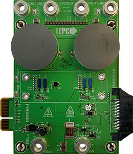
| EPC9137 Power Module | EPC9528 Controller Card | |||||
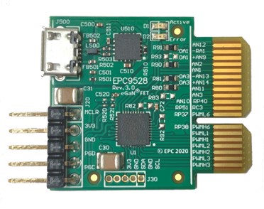
Table of Contents
Summary
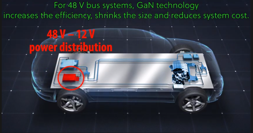
Mild hybridization of vehicles utilizes 48V systems with improved fuel economy and reduced emissions at relatively low cost. This approach provides another, effective and affordable transition point between conventional combustion engines and full electric cars. 48V hybridization aids the internal combustion engines increasing efficiency by driving auxiliary functions such as E-Turbos, regenerative brakes, electronic power steering racks or water pumps, which use electric motors rather than being powered by the engine directly.
Bidirectional 1.5 kW 48-to-12V Bus Converter Introduction Video
Read more...
Despite all obvious advantages of the migration from 12 V to 48 V rail voltage, higher voltages are not beneficial for every load and for other electrical systems cross-platform compatibility prevents fast transition to 48V. Hence, modern mild hybrid vehicles commonly incorporate both, 48 V and 12 V power distribution systems, where 48 V is mainly used for high power loads and power train auxiliary subsystems using energy harvesting methods to recuperate energy storages, while 12 V is still used to power low-power loads and cross-platform electronics such as interior lighting, sensors, actors, driver assistance ECUs or infotainment & navigation. One of the central 48 V combustion engine auxiliary systems is the starter/generator, which is the sole source of electrical power but may not continuously generate energy. Engine boost and recuperation requires additional energy storage capabilities as well as power balancing between 48 V and 12 V rails. This junction point is established by using synchronous multiphase step-up/step-down converters exchanging electrical energy between the energy storages of both rails. The bi-directional EPC9137 evaluation power module is designed for these automotive 48 V / 12 V DC-DC converter applications. It features the EPC2206 eGaN FETs with AEC-Q101 qualification. The compatible controller card (EPC9528) includes the Microchip dsPIC33CK256MP503 16-bit digital signal controller. It is designed to work with various EPC evaluation boards and modules. As a kit it allow users to analyze the efficiency and performance of the power stage in various different configurations, as well as utilizes embedded digital control to establish non-linear operating schemes and modes by incorporating battery charging and constant output voltage control in both directions, enhanced diagnostics for improved functional system safety and a wide range of communication interfaces and protocol stacks to support seamless integration in control systems of various vehicle models. The focus of this evaluation kit lies on power conversion performance, efficiency and basic functional aspects. The board starts up automatically when a voltage between the specified minimum and maximum input voltage is applied across the 48V-input terminals of the EPC9137 power board, providing a regulated output voltage of 12 V DC at the output terminals of the converter. The startup procedure is controlled and executed by the power controller state machine and includes a configurable startup procedure with power-on delay, ramp-up period and power-good delay before dropping into constant regulation mode. #### Fault Management An additional fault handler routine continuously monitors incoming ADC data and peripheral status bits and shuts down the power supply if - the input voltage is outside the defined maximum range (UVLO/OVLO) - the output voltage is more than 0.5 V out of regulation for more than 25 milliseconds - the heat-sink base temperature exceeds 95°C (OTP) - the total output current exceeds 130 A (buck mode) resp. 35 A (boost mode) The converter automatically recovers from all detected fault conditions listed above. #### Product Features - Input Voltage: 17 V to 64 V DC - Output Voltage: 12.0 / 13.2 V DC (12 V default setting) - Switching Frequency: 250 kHz - Control Frequency: 250 kHz - Cross-Over Frequency: ~5 kHz - Phase Margin: ~ 60° - Gain Margin: ~ 12 dB[back]
Related Documentation
Firmware Documentation
- EPC9137 Online Firmware Documentation (coming soon)
Hardware Documentation
Device Support
Featured Microchip Technology Products:
- dsPIC33CK256MP503 Product Website
- MCP6C02 Shunt Amplifier Product Website
- MCP2221A USB 2.0 to I2C/UART Protocol Converter Product Website
Featured Efficient Power Conversion (EPC) Products:
[back]
Development Tools
MPLAB® X Integrated Development Environment (IDE)
MPLAB® XC16 C-Compiler
MPLAB® X PowerSmart™ Digital Control Library Designer
Microchip Power Board Visualizer GUI Supporting dsPIC33® DSCs
[back]
Security and Safety Requirements
Unattended operating power supplies are always a potential safety risk as short circuits or failures of power components can occur at any time where even seemingly small power converters can cause fire or damage connected equipment.
- This development board has not been FCC approved nor certified and must not be used outside a laboratory environment
- Never operate the board unattended
- Only use power supplies delivered with the board or equal, approved laboratory equipment
- Read the user guide for detailed operating instructions to prevent damage to the board or connected equipment
[back]
Regulatory Information
This power module is for evaluation purposes only. It is not a full-featured power module and cannot be used in final products. No EMI test was conducted. It is not FCC approved.
[back]
Demonstration Board Setup
The EPC9137/EPC9528 kit comes programmed in step-down only mode and is ready to be used when unpacked. No reprogramming of the target device is required to operate the board unless features, modes or settings such as the nominal output voltage or start-up timing need to be modified.
The EPC9528 controller card must be plugged into the EPC9137 power module before power is applied to the development kit. The converter is starting up automatically when more than 17 V DC are applied across the 48V input terminals of the EPC9137 power module.
In case firmware based features or operating modes need to be changed, the Microchip dsPIC33CK controller can be re-programmed using the in-circuit serial programming port (ICSP) available on the 5-pin header provided on the EPC9528 Controller Card. This interface supports all of Microchip’s in-circuit programmers/debuggers, such as
- MPLAB® ICD4 (Part-No DV164045)
- MPLAB® REAL ICE (Part-No DV244005)
- MPLAB® PICkit4 (Part-No PG164140)
- MPLAB® Snap (Part-No PG164100)
Please read the EPC9528 Quick Start Guide to get detailed information about the requirements for setup, operation and reprogramming of the controller card.
1) Mounting the Heat Sink
If the heat sink has not been mounted yet, it is highly recommended to assemble it before high power test procedures are performed. Without heat sink there is a high risk of thermal overstress, shortening the lifetime of the development kit and baring the risk of irreversible damage.
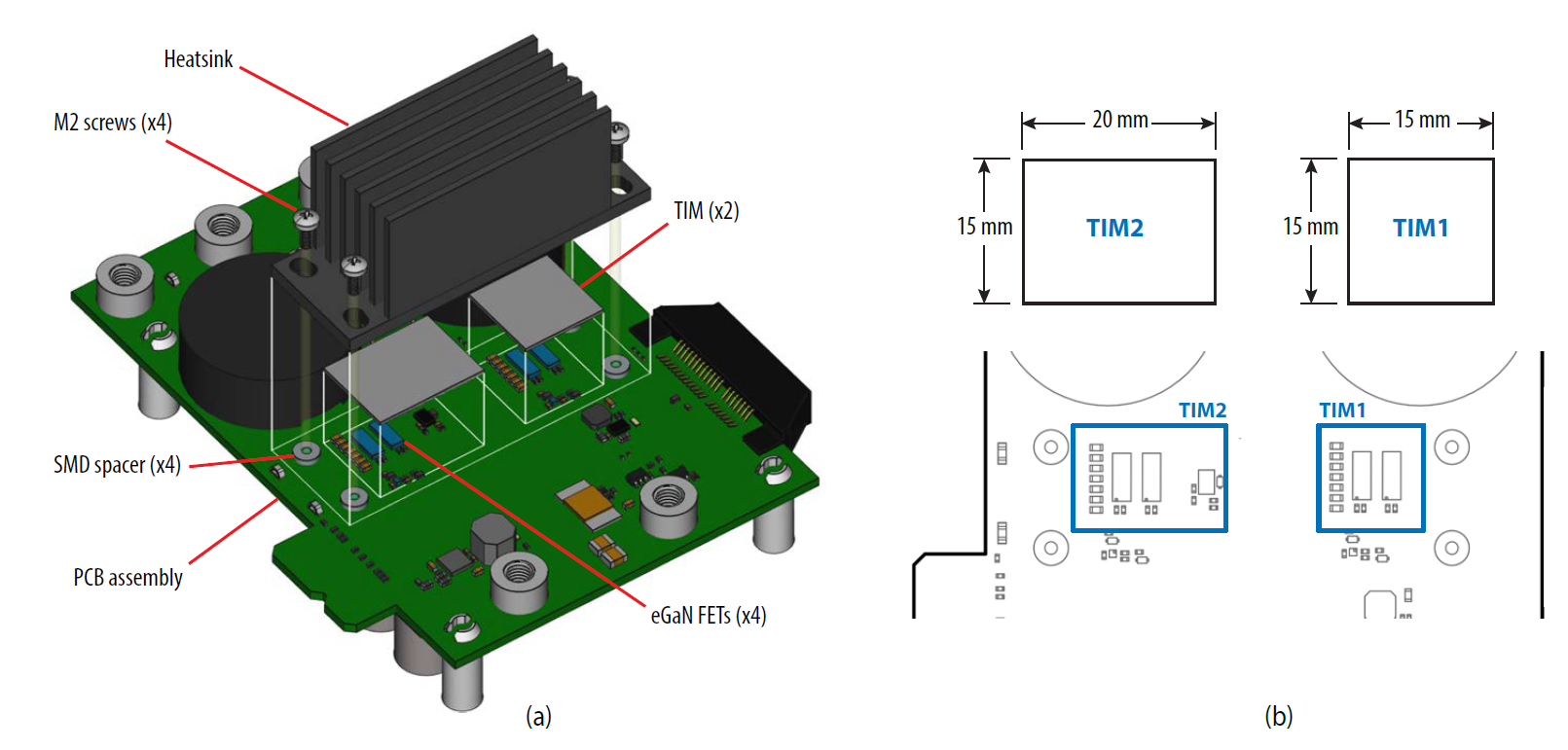
EPC9137 Heat Sink Assembly
Please read the user guide for more detailed instructions on the proper mounting procedure.
[back]
2) Buck Mode Operation
This is the default setup supported by the firmware provided. When connected to a DC bench supply and load, this kit can be operated as standard, fixed output voltage 48V-to-12V step down converter. If the output is driven into current limit at 125 A of output current, the converter will drop into constant current mode until the output voltage drops below 7V.
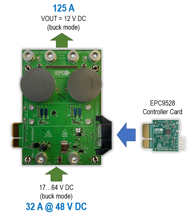
EPC9137 Buck Mode Setup
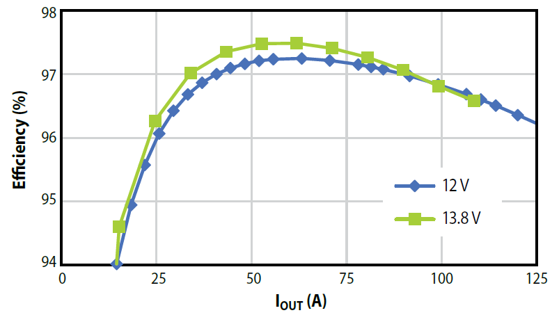
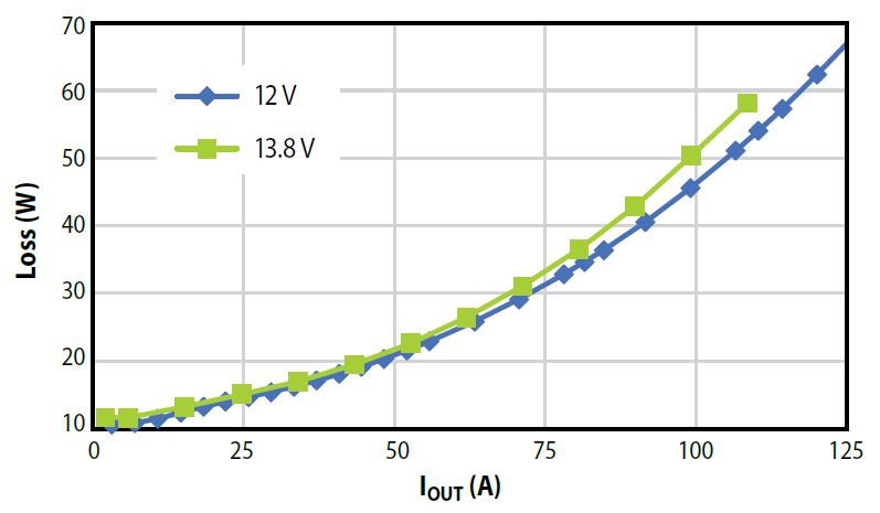
ELECTRICAL PERFORMANCE / TEST RESULTS
Test Conditions: VIN = 48 V DC
Show Details...
|
|
||
| EPC9137 Buck Mode Efficiency | EPC9137 Buck Mode Losses | ||
|
|
||
|
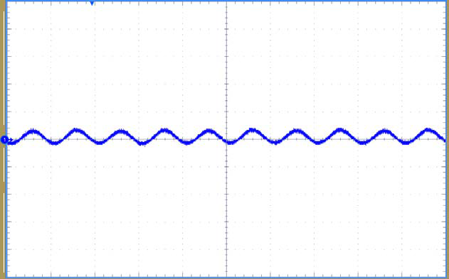
EPC9137 Buck Mode Output Voltage Ripple (2 µs/div, 100 mV/div) |
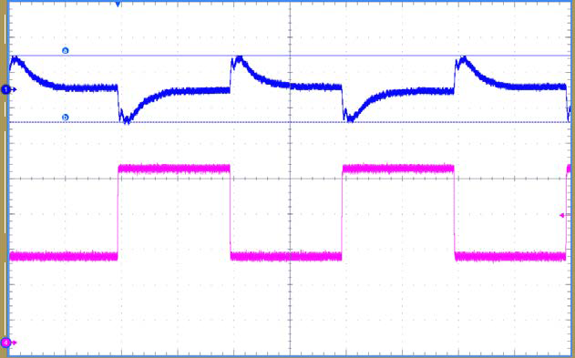
EPC9137 Buck Mode Transient Response @ VOUT = 12 V [ VOUT , IOUT] (2 ms/div, 500 mV/div, 6 A/div) |
||
|
<tdstyle="border: none;"> </td>
|||
|
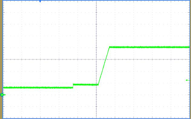
EPC9137 Buck Mode Output Voltage Startup Timing (100 ms/div, 3 V/div) |
|||
[back]
3) Boost Mode Operation
In boost mode, the converter starts up as soon as input voltage between 9 V DC and 18 V DC is applied to the 12 V DC terminals of EPC9137.
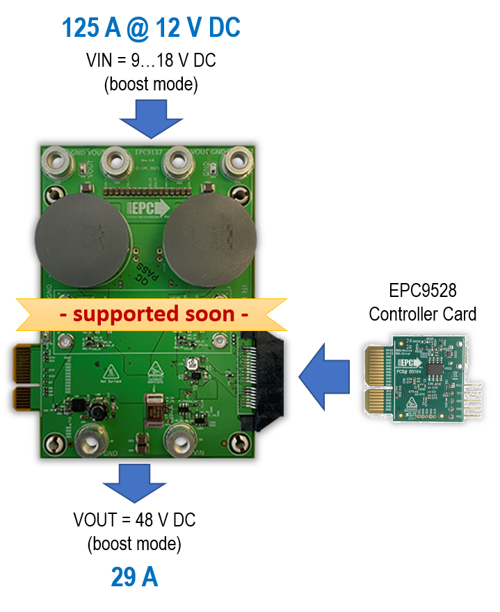
EPC9137 Boost Mode Setup
ELECTRICAL PERFORMANCE / TEST RESULTS
Test Conditions: VIN = 12 V DC
Show Details...
*(test results not available in this firmware release)*[back]
4) 4-Phase Operation
The EPC9137/EPC9528 kit allows paralleling of up to two EPC9137 power modules controlled by one EPC9528 controller card. In this configuration the kit can provide up to 250 A of output current (= 3 kW @ VOUT = 12 V DC).
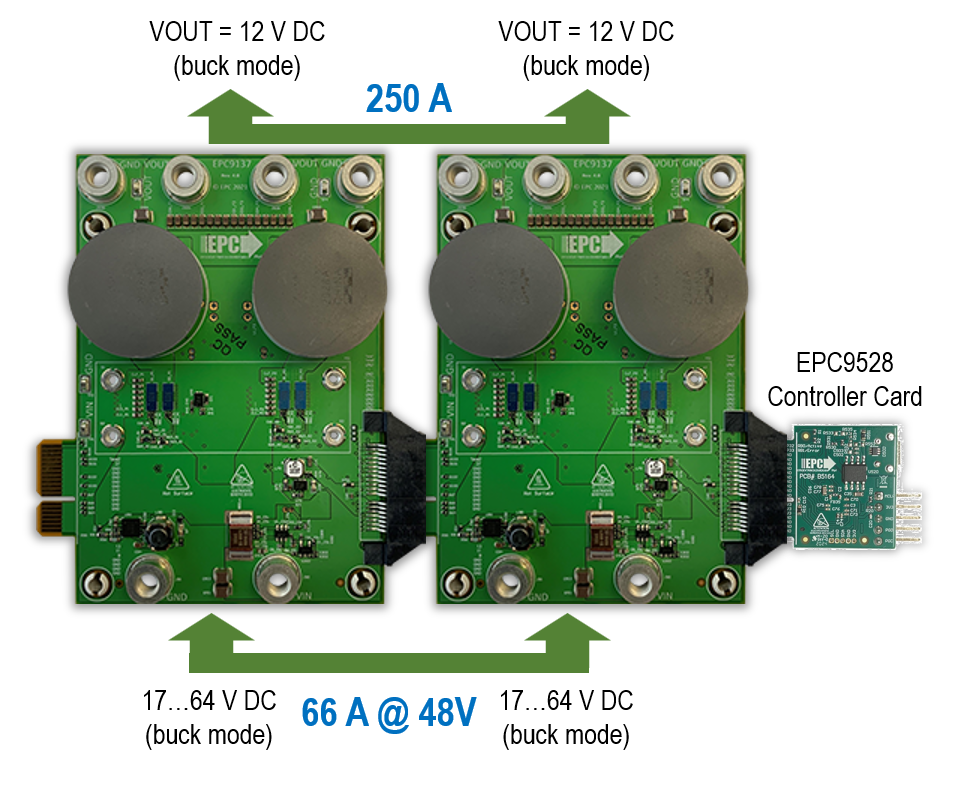
EPC9137 4-Phase Converter Setup
ELECTRICAL PERFORMANCE / TEST RESULTS
Test Conditions: VIN = 48 V DC
Show Details...
*(test results not available in this firmware release)*[back]
5) Loop Test Operation
To simplify test procedures and allow long-term testing with reduced power consumption, two EPC9137/EPC9528 kits can be operated in counter-wise step-down/step-up mode, effectively circling power through both converters. Due to the inevitable power losses, an additional auxiliary power supply (e.g. bench power supply) must be connected to either 48 V- or 12 V-rail side to keep the operation going. It is recommended to buffer both bus rails with larger off-board capacitors to balance the 12 V versus the 48 V bus.
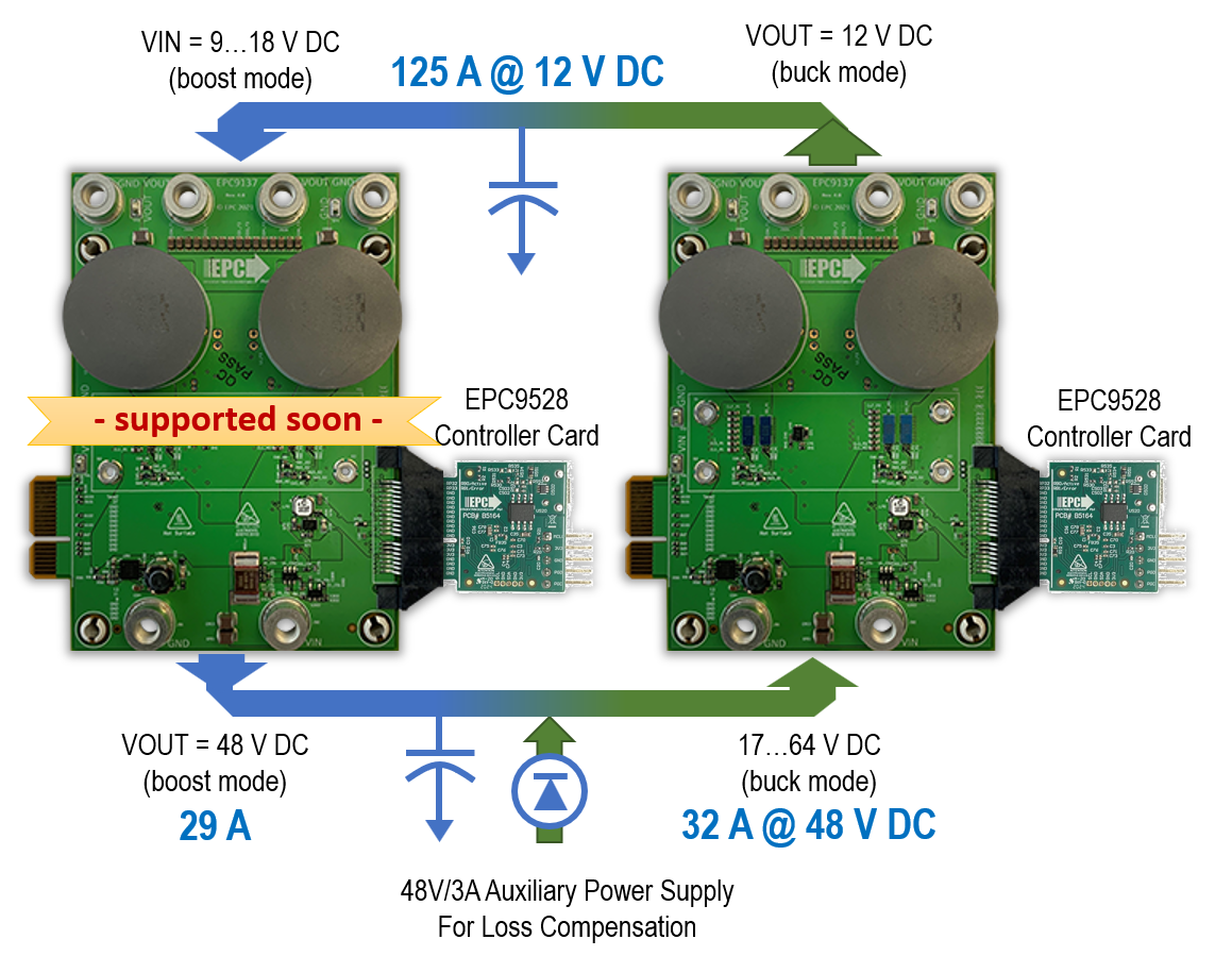
EPC9137 Loop Test Mode Setup
ELECTRICAL PERFORMANCE / TEST RESULTS
Test Conditions: VIN = 48 V DC
Show Details...
*(test results not available in this firmware release)*[back]
Firmware Quick-Start Guide
This firmware is built on Microchip’s PowerSmart™ Digital Power Firmware Framework. Unified code architectures with selectable building blocks from Operating Systems, Diagnostics Layers to generic and scalable Power Control State Machines and Discrete Feedback Loop Library are supporting the modular nature of this development kit but also the necessary scalability for tailoring standard hard- and software platforms to custom solutions for production.
1) Buck Converter State Machine
The buck converter device driver used in this firmware example is written as feature-rich generic device driver library module providing seamless hardware and microcontroller migration providing users with a high degree of portability and scalability with minimum firmware qualification.
Show details...
The state machine goes through the following steps in chronological order: ##### a) Initialization In this step the control loop parameters are reset to their defaults, PWM outputs are turned off but the PWM generators are still running, continuously triggering the ADC sampling input and output voltage as well as board temperature. ##### b) Reset This is the 'fall-back' state from which the buck converter will be restarted once it has been started successfully and has been shut down due to a fault condition (e.g. input under/over voltage or over temperature condition) ##### c) Standby After `RESET`, the state machine waits for all fault flags to be cleared and the `ENABLE` and `GO` bits to be set. ##### d) Power-On Delay (POD) Once the buck converter has been cleared the state machine will execute the startup procedure starting with the Power On Delay. This is just a simple delay during which the converter will remain inactive but the fault handler will observe the values generated by the ADC for occurring fault conditions. ##### e) Launch Voltage Ramp After the Power-On delay has expired, input and output voltage will be measured. In case the converter output is pre-biased (voltage = non-zero), the power controller will be 'pre-charged' with an artificial control history and PWM output to softly ramp up the output voltage from its most recent level. ##### f) Voltage Ramp-Up Now the digital feedback loop and PWM module are enabled and the closed loop system reference value is incremented with every execution of the state machine (default: 100 µsec interval). In average current mode control only the voltage reference is incremented until the output voltage matches the specified reference level. ##### g) Current Ramp-Up When powering up against highly capacitive loads, such as a large number of discharged decoupling and input capacitors of the down-stream power distribution network, or batteries, maximum startup current is limited. When the converter powers up against a discharged battery, the feedback loop might run into a current limit condition during Voltage Ramp-Up. In this case, the state machine will switch over to Current Ramp-Up, now incrementing the current reference limit up to a user-specified value. This current limit mode can be used to implement specific battery charging profiles for different chemistries. At the end of the charging period, the current loop will decrease its output as soon as the outer voltage loop is limiting the output voltage level. This point marks the seamless switch-over into constant voltage mode, at which the converter acts like a conventional, constant voltage source DC/DC converter ##### h) Power Good Delay After the reference voltage has been increased to the pre-defined nominal level, the state machine switches over into the Power Good Delay period. This is another, simple delay where the control loop is in steady state waiting for the delay period to expire. ##### i) Online After the Power Good Delay has expired, the converter drops into nominal operation. In this condition it continuously observes the reference value for changes. Should any other part of the firmware change the controller reference, the state machine will softly tune into the new level instead of hard-switching the reference. ##### j) Suspend/Error If the power controller is shut down and reset by external commands (e.g. fault handler detecting a fault condition or through user-interaction), the state machine is switching into the `SUSPEND` state, which disables the PWM outputs and control loop execution, clears the control histories and resets the state machine back to `RESET`[back]
2) Cycle-by-Cycle Current Mode Control Loop
The bi-directional control system of EPC9137 is based on the conventional Average Current Mode Control (ACMC). An outer, discrete type III (3P3Z) voltage loop regulates the output voltage by comparing the most recent feedback value against an internally defined reference value (software). The deviation is processed by a discrete type II (2P2Z) compensation filter. The output of the voltage loop sets the reference for the two inner current loops. Each phase current controller processes the deviation between the given dynamic current reference and the individual, most recent current feedback. Each current control loop output adjusts the individual duty cycle resulting in tightly balanced phase currents. This control scheme is applied to both, 48 V to 12 V downstream buck as well as to 12 V to 48 V upstream boost operation.
Show details...
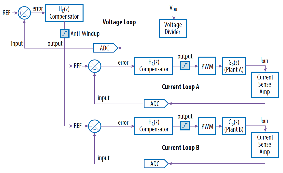
EPC9137 Average Current Mode Control Loop
[back]
3) User Control Interface
No user control interface has been added to the firmware. Any change to the firmware and fundamental operation of the reference design, including reprogramming of the nominal output voltage can be done by editing the hardware-specific values in the hardware description header file epc9137_r40_hwdescr.h located in ‘Project Manager => Header Files/Config’
Show details...
Converter settings in this file are defined as physical quantities such as Volt, Ampere, Ohm, etc. Each defined value is converted into binary numbers by so-called macros, at compile time. Thus, users do not have to convert values manually. ##### Example: To program the converter to provide a nominal output voltage different from the 12 V DC set by default, follow these steps: - Open the project in MPLAB X® IDE - Navigate to 'Header Files/Config/epc9137_r10_hwdescr.h' using the Project Manager on the left side of the main window - Search for marco `BUCK_VOUT_NOMINAL` (see below) - Change the give settings as desired - Build the program - Remove power from the input of the EPC9528 Controller Card - Connect a valid ICSP programming device (e.g. MPLAB ICD4, MPLAB PICkit4) to the PC and the EPC9528 Controller Card (see EPC9528 Quick Start Guide for details) - Program the device with the target device being powered by the debugger/programmer - Disconnect the ICSP programming device from the EPC9528 Controller Card - Apply valid input voltage across the input terminals and observe the output of the EPC9137 power module The setting for the nominal output voltage is found in the output voltage parameters declaration section. ```c #define BUCK_VOUT_NOMINAL (float)12.000 // Nominal output voltage #define BUCK_VOUT_TOLERANCE_MAX (float)0.500 // Output voltage tolerance [+/-] #define BUCK_VOUT_TOLERANCE_MIN (float)0.100 // Output voltage tolerance [+/-] ``` ##### Please note The tolerance settings above include the transient response at a maximum load step. The value for maximum output voltage tolerance `BUCK_VOUT_TOLERANCE_MAX` is observed by the fault handler. Should the output voltage reading divert from the most recent reference voltage value by more than the given range, the converter will be shut down and a `REGULATION ERROR` will be indicated. The power supply will automatically recover as soon as the fault condition has been cleared and the recover delay period specified by `BUCK_REGERR_RECOVERY_DELAY`, declared in the EPC9137 hardware description header file, has expired.[back]
4) Power Plant Measurement Support
This code example includes an alternative, proportional control loop which is commonly used during measurements of the frequency response of the power plant. When the following define is set to TRUE, the common main control loop is replaced by the proportional controller.
epc9137_r40_hwdescr.h: #define PLANT_MEASUREMENT false
Show details...
PLEASE NOTE
PROPORTIONAL CONTROLLERS ARE BY DEFAULT UNSTABLE AND NOT SUITED TO REGULATE THE OUTPUT OF A POWER SUPPLY UNDER NORMAL OPERATING CONDITIONS. DURING A PLANT MEASUREMENT IT IS MANDATORY THAT INPUT VOLTAGE AND LOAD REMAIN STABLE AND DO NOT CHANGE.
FOR MORE INFORMATION ABOUT HOW TO CONDUCT A POWER PLANT MEASUREMENT, PLEASE READ THE SECTIONS IN THE PowerSmart™ DCLD USER GUIDE.
[back]
© 2021, Microchip Technology Inc.